Iranian Classification Society Rules

< Previous | Contents | Next >
ANNEX 2 Load cases for propeller and the shape of the propeller ice torque excitation for the ships strengthened for
navigation in ice and polar class ships
![]()
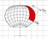
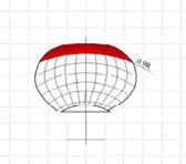
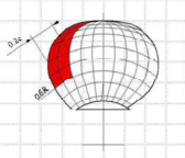
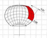
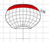
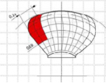
Table 2.1 Load cases for open propeller
Load case | Force | Loaded area | Right handed propeller blade seen from back |
Load case 1 | Uniform pressure applied on the back of the blade(suction side) to an area from 0.6 to the tip and from the leading edge to 0.2 times the chord length | ||
Load case 2 | 50% of | Uniform pressure applied on the back of the blade(suction side) on the pro- peller tip area outside of 0.9 radius | |
Load case 3 | Uniform pressure applied on the blade face (pressure side) to an area from 0.6 to the tip and from the leading edge to 0.2 times the chord length |
| |
Load case 4 | 50% of | Uniform pressure applied on the pro- peller face (pressure side) on the pro- peller tip area outside of 0.9 radius |
|
Load case 5 | 60% of or which is greater | Uniform pressure applied on the pro- peller face (pressure side) to an area from 0.6 to the tip and from the trailing edge to 0.2 times the chord length |
Annex 2 Load Cases for Propeller and the Shape of the Propeller Ice Torque Excitation
for the Ships Strengthened for Navigation in Ice and Polar Class Ships Annex 2
![]()
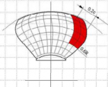
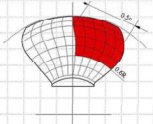
Table 2.2 Load cases for ducted propeller
Load case | Force | Loaded area | Right handed propeller blade seen from back |
Load case 1 | Uniform pressure applied o the back of the blade(suction side) to an area from 0.6 to the tip and from the leading edge to 0.2 times the chord length | ||
Load case 3 | Uniform pressure applied on the blade face (pressure side) to an area from 0.6 to the tip and from the leading edge to 0.5 times the chord length |
| |
Load case 5 | 60% of or which is greater | Uniform pressure applied on the pro- peller face (pressure side) to an area from 0.6 to the tip and from the trailing edge to 0.2 times the chord length |
1,2
1
0,8
0,6
0,4
0,2
0
0 90 180 270 360 450 540 630 720
Angle of rotation [deg]
1,2
1
0,8
0,6
0,4
0,2
0

1,2 1,
2
1 1
0,8 0,
8
Ice block 2
Ice block 1
0,6
0,4
0,2
0,6
0,4
0,2
0
0 90 180 270 360 450 540 630 720
Angle of rotation [deg]
0
0 90 180 270 360 450 540 630 720
Angle of rotation [deg]
![]()
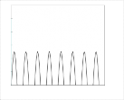
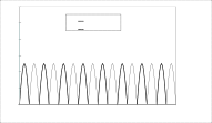
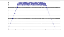
Fig 2.1 The shape of the propeller ice torque excitation for 45, 90, 135 degrees single blade impact sequences and 45 degrees double blade impact sequence(two ice pieces) on a four-blade pro- peller
![]()
1
0,9
0,8
0,7
0,6
0,5
0,4
0,3
0,2
0,1
0
0 200 400 600 800 1000 1200 1400
1
0,9
0,8
0,7
0,6
0,5
0,4
0,3
0,2
0,1
0
0 200 400 60 0 800 1000 1200 14 00
1
0,9
0,8
0,7
0,6
0,5
0,4
0,3
0,2
0,1
0
0 200 400 600 800 1000 1200 1400
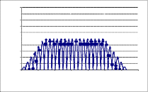
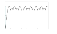
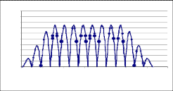
Fig 2.2 The shape of the propeller ice torque excitation for 90, and 135 degree single-blade impact
![]()
sequences blades.)
and 45 degree double-blade impact sequence. (Figures apply for propellers with 4
![]()